Valve Testing Equipment

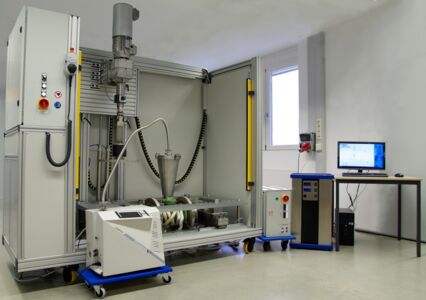
In order to be able to verify and further optimize the tightness and function of the stem seals and housing cover seals of valves, we have developed the valve test stand TEMESvalve.teq.
Standards included: API, ISO, VDI
Testing can be carried out according to standards like
- API 641
- API 624
- API 622
- DIN EN ISO 15848-1
- VDI 2440
- API 607
- DIN EN ISO 10497
- user defined procedures
Friction forces during stem actuation are quantified as well as leakage rates for different sealing materials and assembly conditions.
Layout of the test rig
The test rig TEMESvalve.teq is suitable to valve sizes DN150/PN150 or DN250/PN25 (6"/10"), in standard configuration.
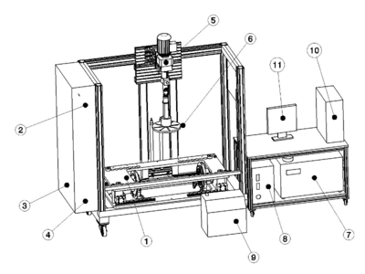
It consists of the mechanical assembly (base frame with clamping device), electric stem drive mechanism, heating and cooling device, control cabinet, leakage device, PC and monitor.
A leak detector is available as optional accessory.
- clamping device
- control cabinet
- hydraulic pump
- leakage device
- stem drive mechanism
- clutch
- cooling device
- heating device
- leak detector
- PC
- monitor
The heating device is suitable for temperatures up to 400 °C (750 °F). Leakage tests can be performed with pressures up to 200 bar (2.900 psi) within the full temperature range.
TEMESvalve.teq is suitable for different leakage measurement methods:
- differential pressure decay
- Helium leak detector or a
- flame ionization detector (FID)
are different options to meet your requirements. The test rig is prepared for the measurement of leak rates with different test media, like Nitrogen, Helium and Methane.
Computer based data logging enables a complete recording of all relevant variables. Individual online diagrams and alphanumerical indicators are available for online monitoring of the test procedures. Data storage is compatible with MS Excel for customer-specific or application-specific reporting.
The software additionally facilitates automated test procedures and single steps thereof. Measured data including switch settings of the control unit is continually checked for validity and failure criteria, while displayed on the monitor screen. An alarm signal or automatic switching operation is triggered, if necessary, in order to prevent imminent danger or damages to the test rig.
Test procedures can be performed manually or automated with a PC interface.
Predefined test procedures are available and can be modified or upgraded individually.

